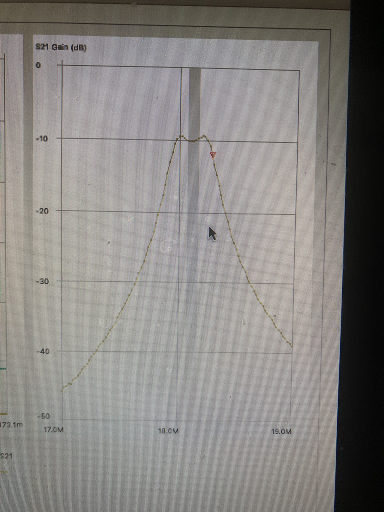
Having added the trimmer caps to the BPF I still had issues, the filter was off band and I couldn’t quite work out why, I fiddled a bit, replaced one of the variable caps which wasn’t measuring correctly, and then decided to model the filter in LTSpice to reproduce my VNA findings.
First of all I reproduced the schematic (with a 50 Ohm load). C3 and C6 represent the variable capacitors, adjusting them to 35pF brings the filter on band.
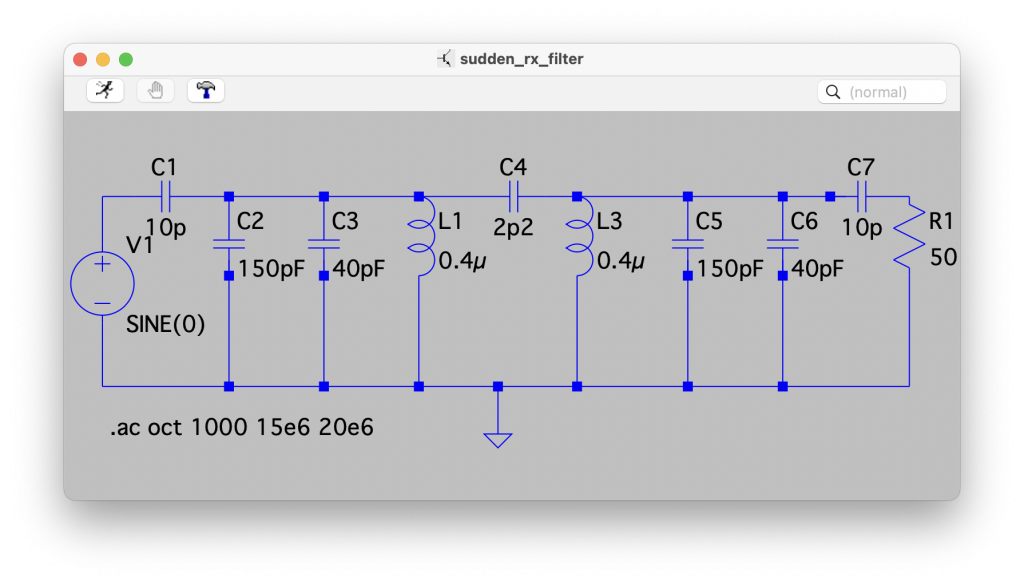
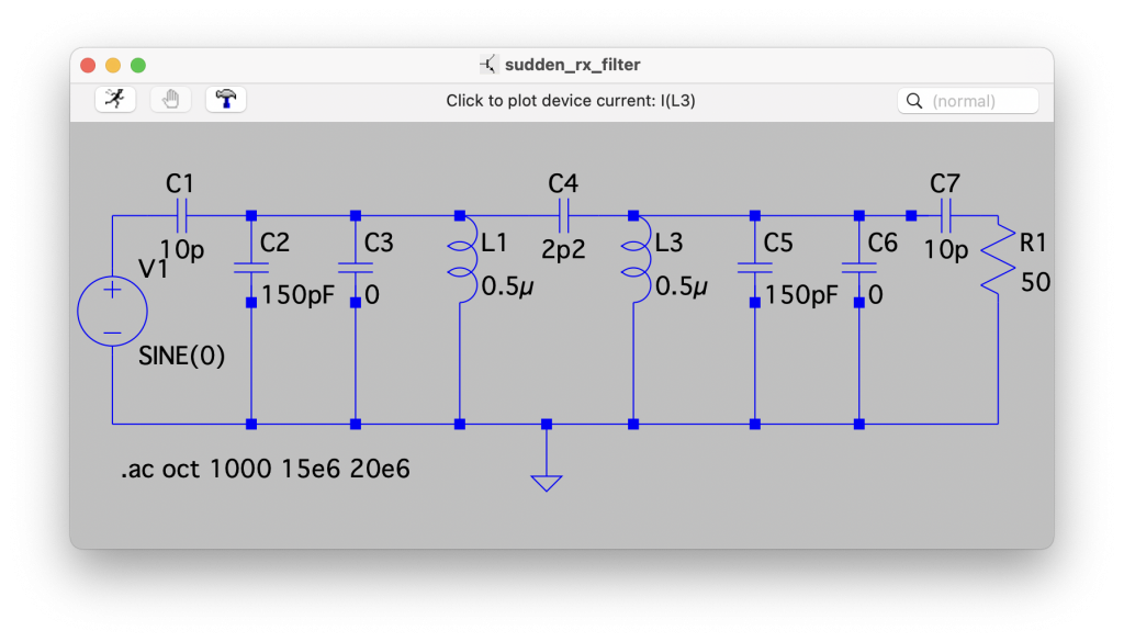
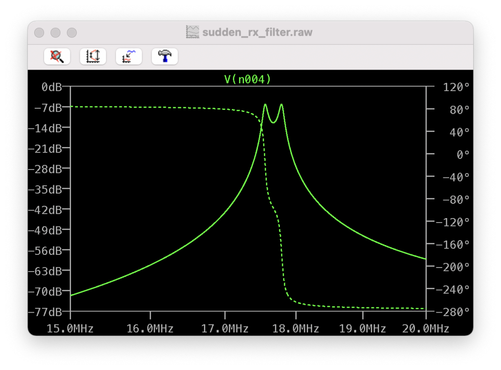
I managed to reproduce my problem by changing the 150pF capacitors (C2 and C5 below) to about 190pF, however I was fairly confident in those components, so I played with the inductor values and managed to reproduce my VNA findings almost exactly by adjusting the values from 0.4µ to 0.5µ.
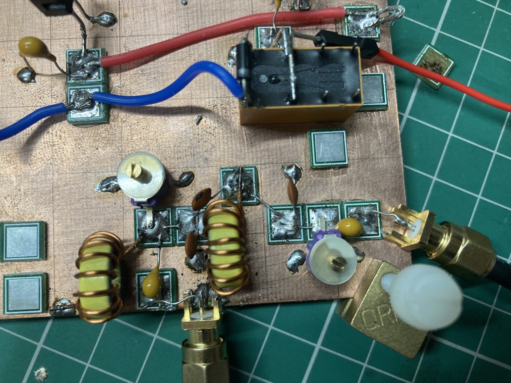
A closer examination of my filter and it became clear that the issue was the windings on the inductors which were too closely placed, once I spaced them out further I was able to get the filter on band.