Sudden SSB N6QW Transceiver

IF Board

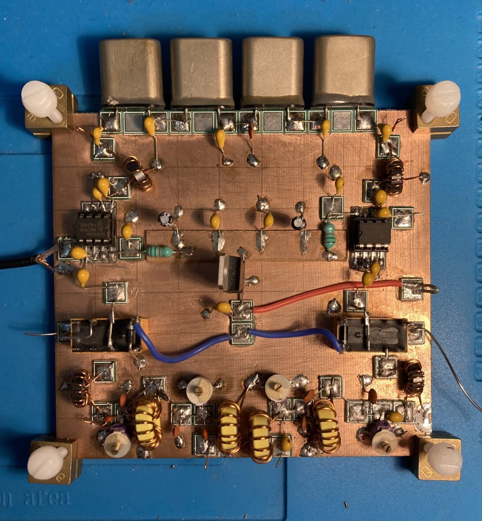
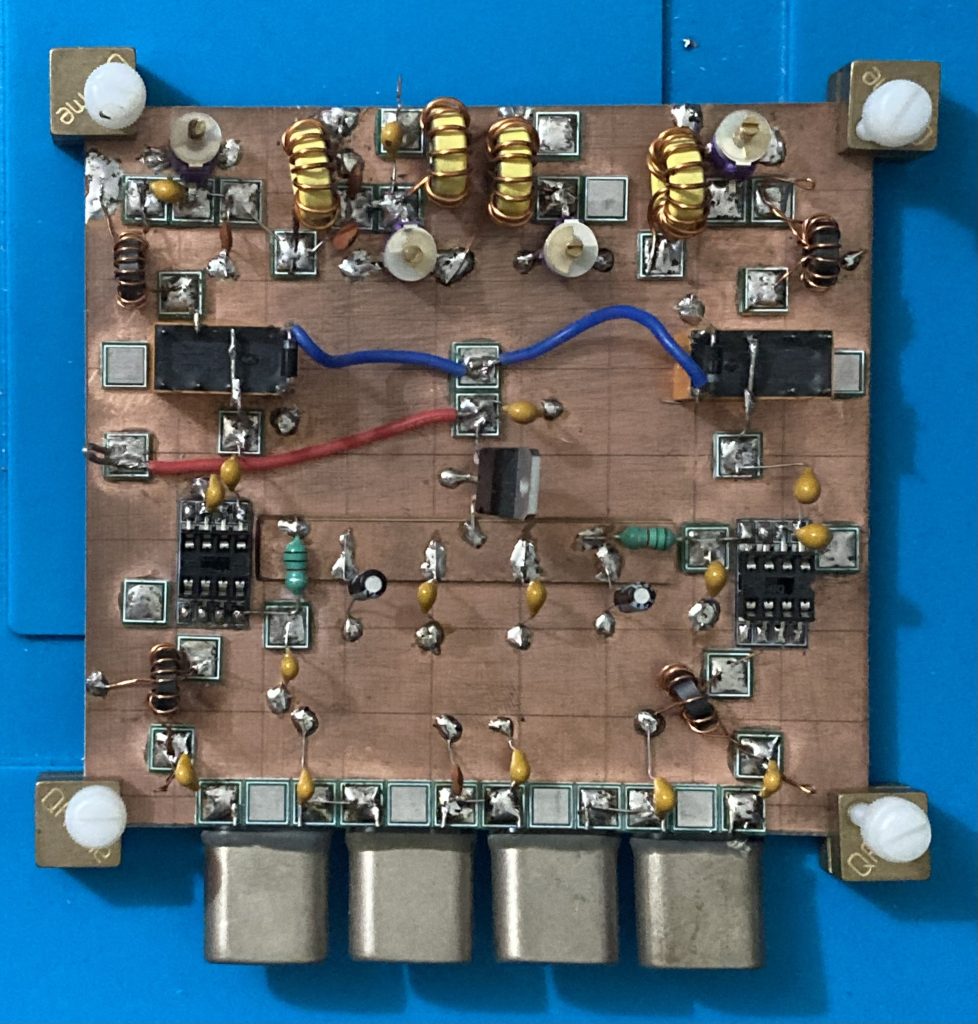
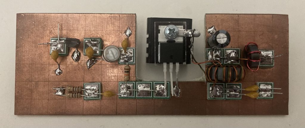
I’ve added the remaining components to the IF board, so I’ll need to get on with testing it at some point, I’m bound to have missed something or got something connected incorrectly. As I added the remaining components I realised that I’d managed to miss the 3p3 capacitor from my last order so that delayed completion, however I also had a bunch of components for the two-tone tester to order anyway.

IF Board Progress

My sudden SSB TRx is long overdue some work and I’ve finally make a little progress, I’m missing a few components but got the remainder of the toroids wound and installed and added the capacitors for the crystal filter. Once the other components have arrived I’ll finish this off, I’ve also ordered the components for the s-meter driver and two-tone tester so I can make a start on them.

Low Pass Filter

The LPF really goes together with the PA, in the GQRP Scratch QRP documents it suggests building and testing them together, however I hadn’t worked out which capacitors I was going to use so I built and tested the PA and then the relays before coming back to this. In the end I used some silver mica capacitors which I purchased from Hifi Collective, they are a little pricey compared to normal capacitors, however they had the values I required so no doubling up etc required and they more than meet the requirements.

No huge issues with this build apart from removing the enamel from the wire for the inductors, burning off with the soldering iron is my preferred method, however I still struggle to get it burnt off enough and clean enough to easily solder. My connections seem decent but I feel like either I’m doing something wrong or there must be a better way, yet scraping off with a knife or using sandpaper seems slow and a bit ’iffy’.

Relay Board

I’ve got moving a bit again on the sudden transceiver project, after completing the PA earlier in the week I’ve got the relay switch board sorted and tested, this switches both the antenna (relay on the left) and 12V supply (relay on the right) between the RX and TX chains and sets the D4 pin on the Arduino high to tell the VFO/BFO module when we are transmitting.

Sudden Power Amplifier

So five months on from preparing the board I’ve FINALLY got round to completing the PA, I had a couple of hiccups but no huge dramas, other than a short circuit which lead to some smoking wires!

First of all despite getting the voltages where I expected I wasn’t getting any current flow, with the help of one of the club members, Dave G8KBB, we discovered that I had a dodgy solder joint, one of the wires I was using too connect a couple of MeSquares wasn’t soldered down air one end, we then discovered that I didn’t have the threshold voltage right, once we discovered that it started working very nicely.

I’ve attached the IRF510 to a heatsink to keep my mounting options open, but most likely I’ll get a metal case and bolt it to that, if not I’ll keep the heatsink, detach the solder tag, bend the middle leg up and attach via a piece of wire.

Sudden Power Amplifier Board Prep


While I’m off the air I thought I’d start preparing the PCB for the next portion of the sudden transceiver which I’m (very slowly) building, the power amplifier. I’ve not really been working on this project just due to lack of spare time at the moment as I’m focusing on CW operation while the bands are good, I know that during the winter I’ll struggle with my evenings on 20 and 40 meters, although I might try to put together an 80m compromise antenna in the loft or across the garden for the winter.