After a period of procrastination I’ve been forced to take a short pause on the IF board whilst waiting for some enamelled copper wire of the right SWG to arrive for the toroids, so thought I’d make a start on the VFO/BFO module.
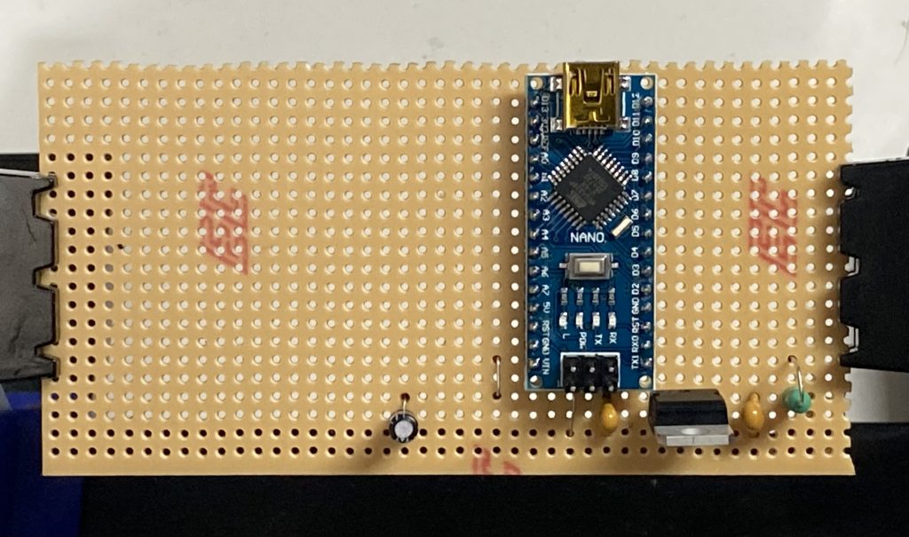
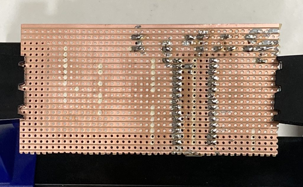
When I originally prepared the board I didn’t test the breaks in the traces for continuity, so before placing the components I checked them and there were a number of breaks which had continuity. After sorting the continuity I placed the power regulator first (and tested it), I then started to place the rest of the components.
I’m not all that happy with some of the soldering on this but I think its good enough and shouldn’t need redoing.