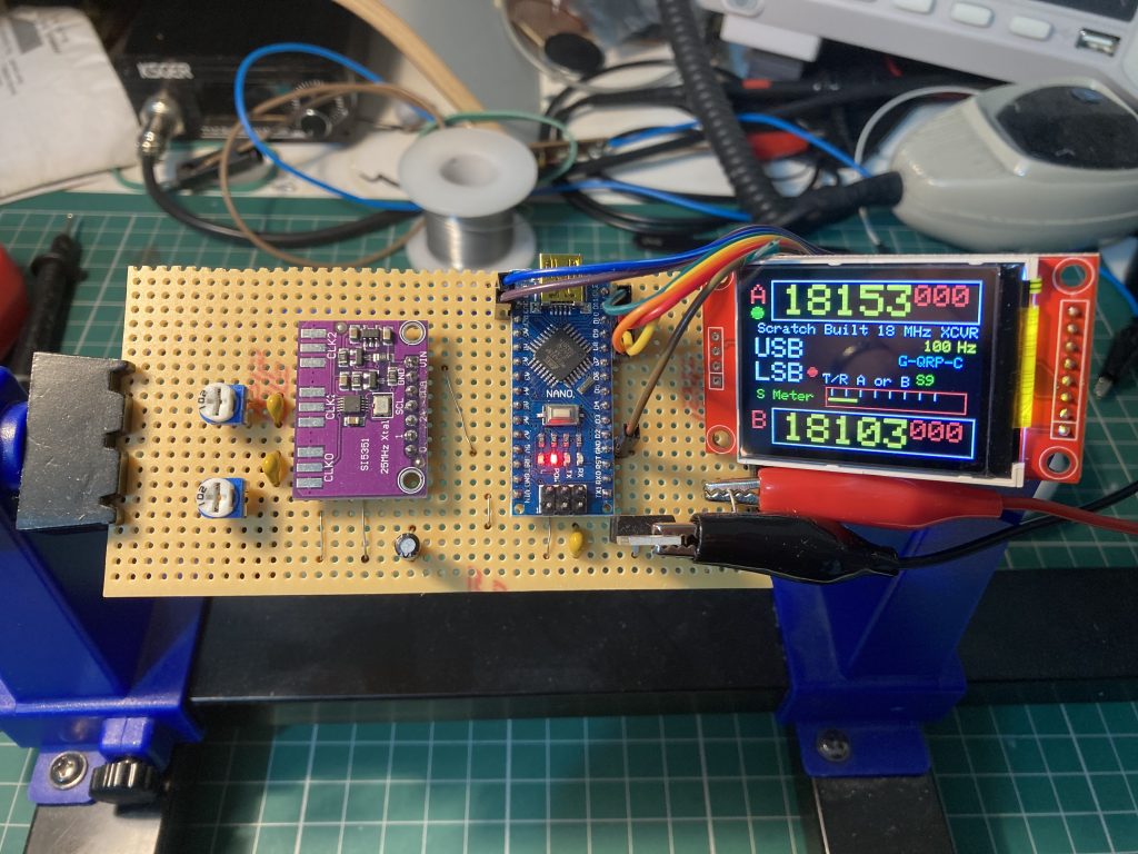
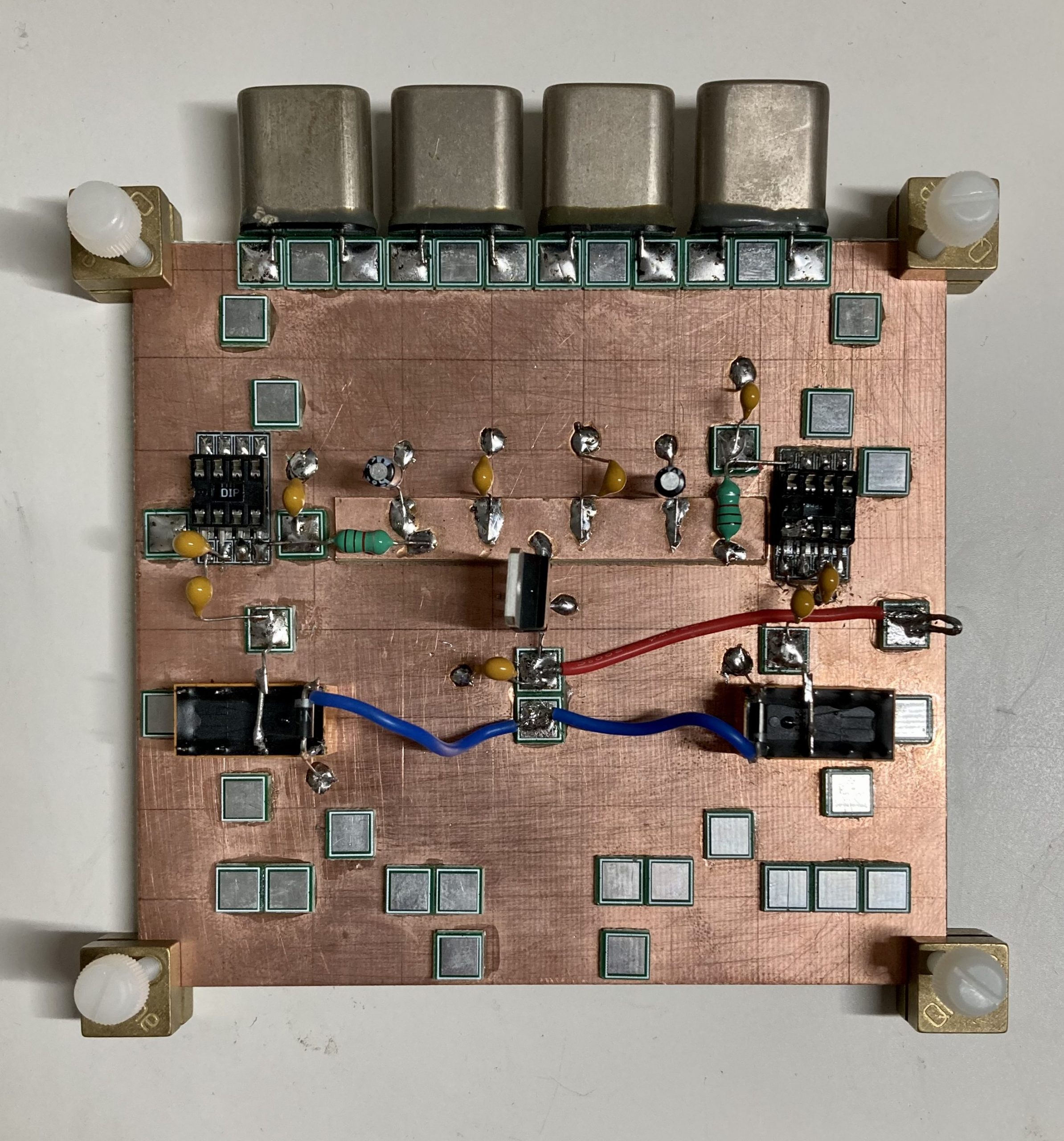
So I finally got round to uploading the sketch to the Arduino and successfully loaded up the VFO/BFO. The sketch uploaded without any issues, it was a simple process and it all works correctly, just needs properly calibrating at some point.
So I finally got round to uploading the sketch to the Arduino and successfully loaded up the VFO/BFO. The sketch uploaded without any issues, it was a simple process and it all works correctly, just needs properly calibrating at some point.
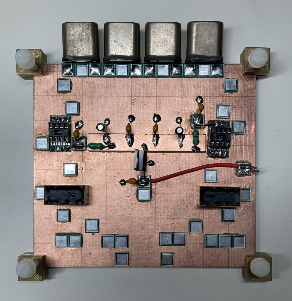
A little more progress on the VFO/BFO, I’ve completed the “build” and now need to upload the sketch to the Arduino, I’m just awaiting a USB C to Mini USB cable to connect it to my laptop. Once I’ve got the cable I’ll be able to setup the software and test the VFO/BFO.

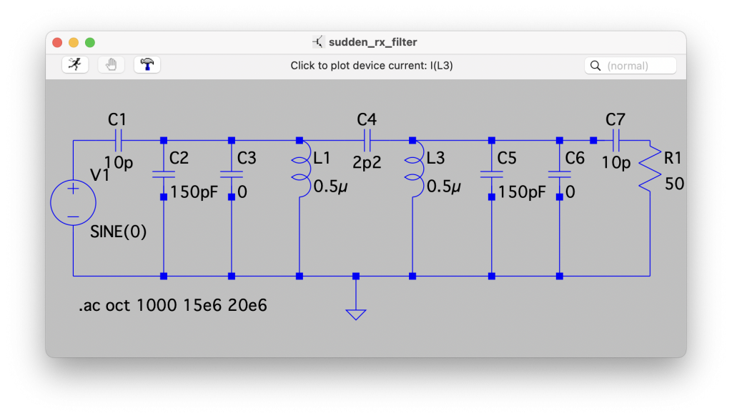
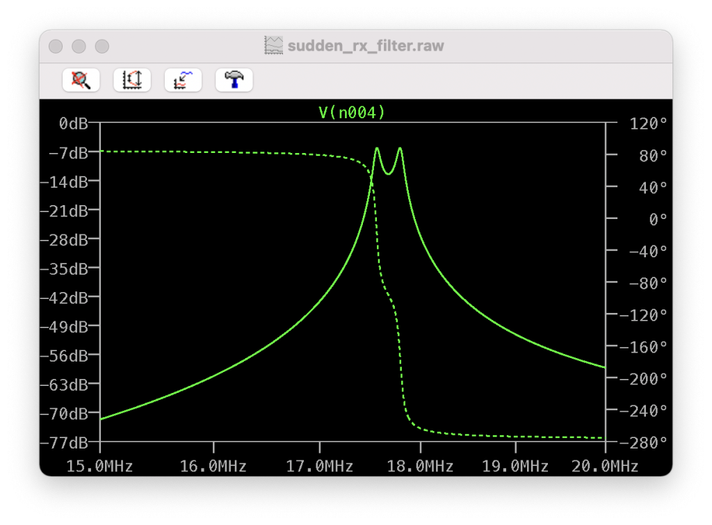
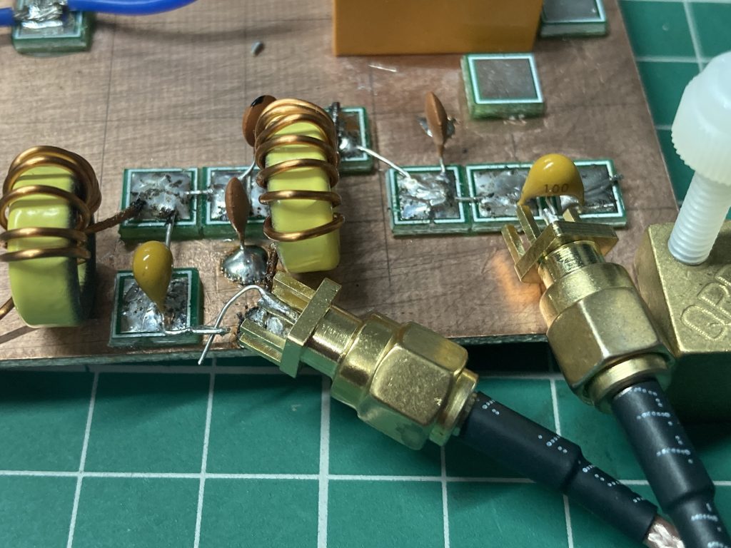
Having added the trimmer caps to the BPF I still had issues, the filter was off band and I couldn’t quite work out why, I fiddled a bit, replaced one of the variable caps which wasn’t measuring correctly, and then decided to model the filter in LTSpice to reproduce my VNA findings.
First of all I reproduced the schematic (with a 50 Ohm load). C3 and C6 represent the variable capacitors, adjusting them to 35pF brings the filter on band.
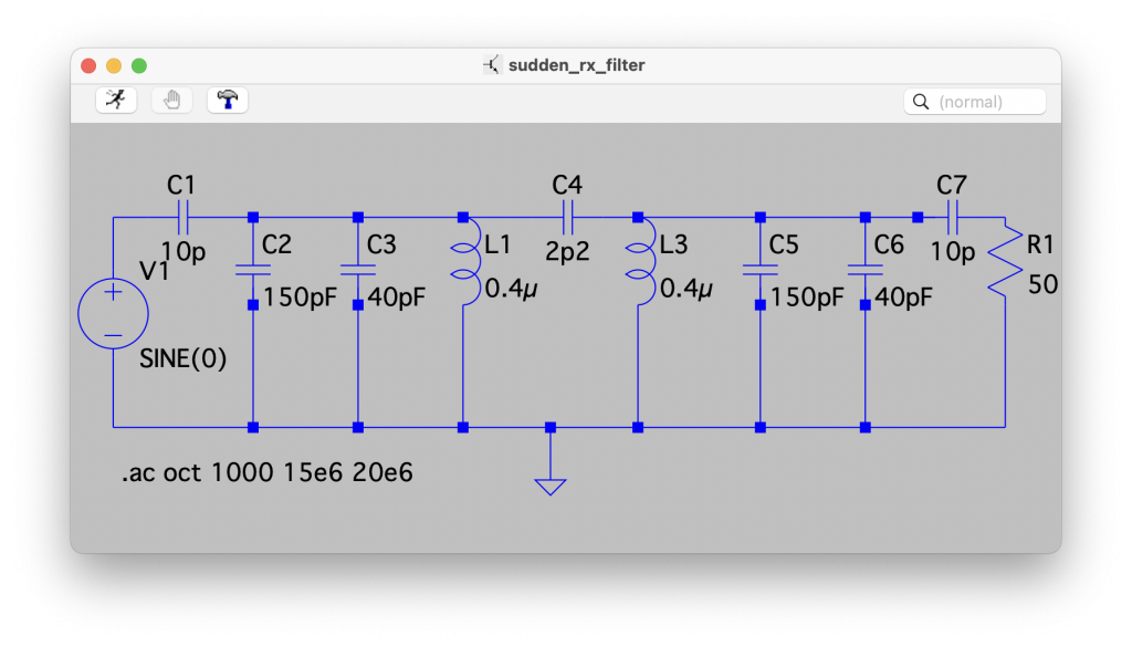
I managed to reproduce my problem by changing the 150pF capacitors (C2 and C5 below) to about 190pF, however I was fairly confident in those components, so I played with the inductor values and managed to reproduce my VNA findings almost exactly by adjusting the values from 0.4µ to 0.5µ.
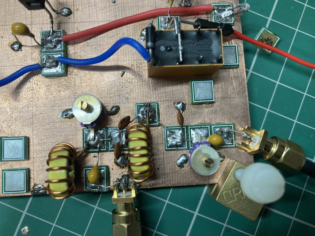
A closer examination of my filter and it became clear that the issue was the windings on the inductors which were too closely placed, once I spaced them out further I was able to get the filter on band.
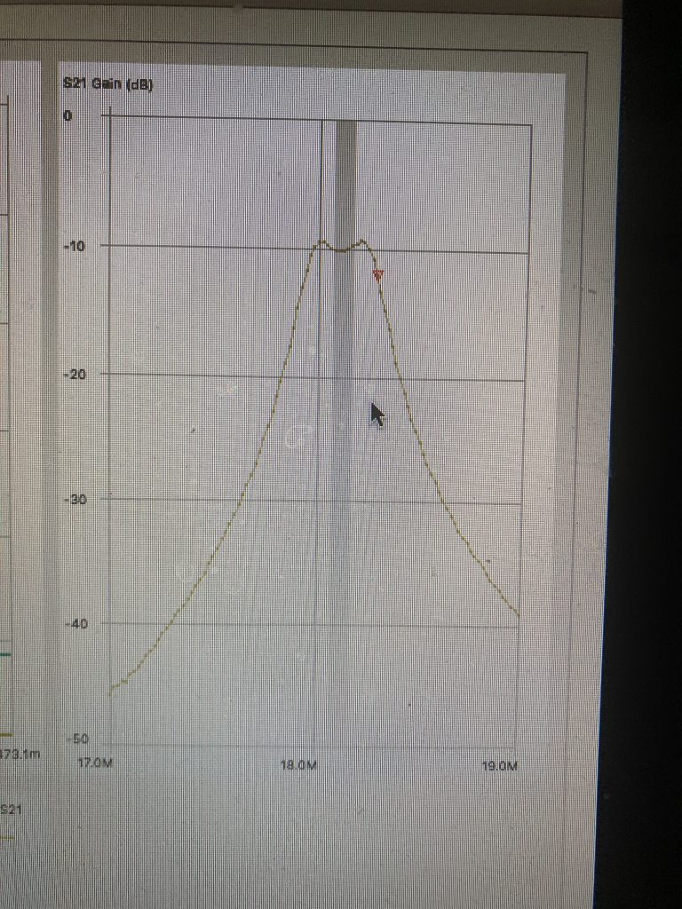
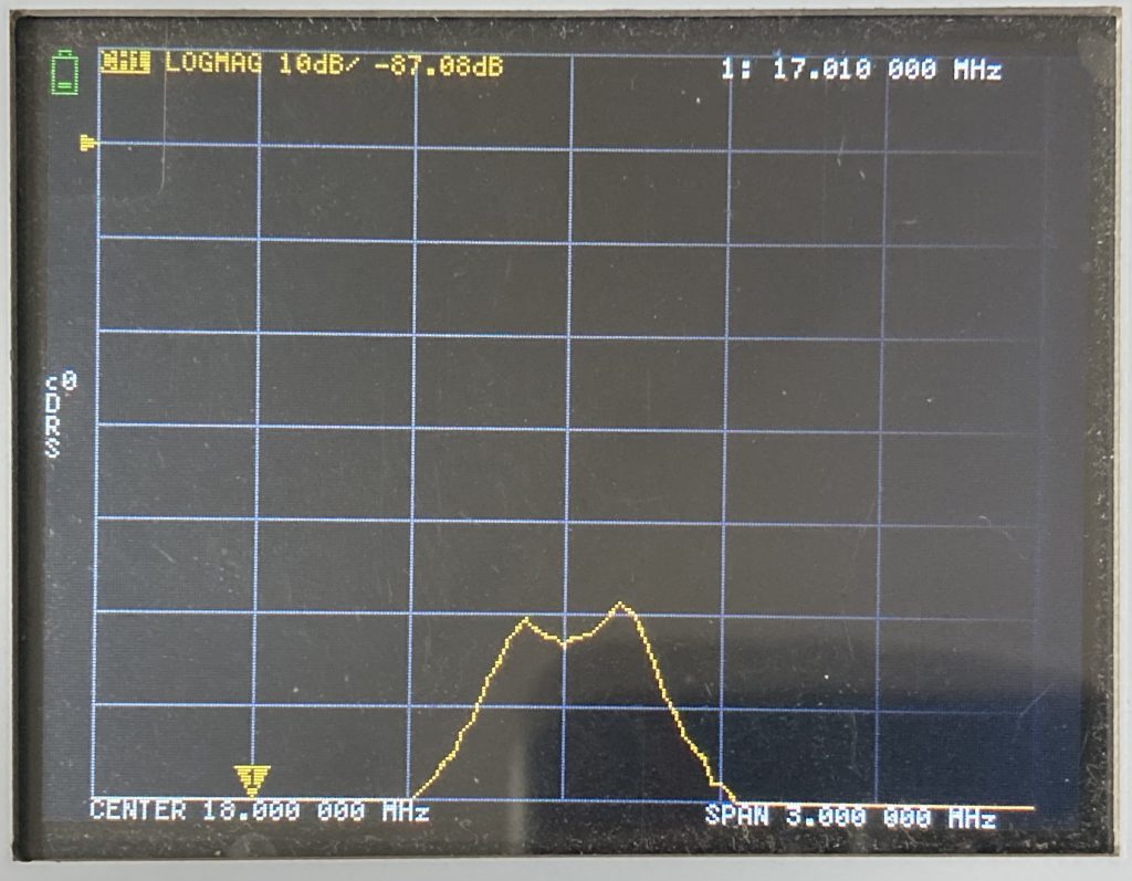
I’ve made a start on the receive BPF on the IF Board, however still having some issues. I am missing the trimmer caps so what I am seeing on the VNA needs to be taken with a giant pinch of salt. I’m encouraged by the shape of the filter but not the losses!
After a period of procrastination I’ve been forced to take a short pause on the IF board whilst waiting for some enamelled copper wire of the right SWG to arrive for the toroids, so thought I’d make a start on the VFO/BFO module.
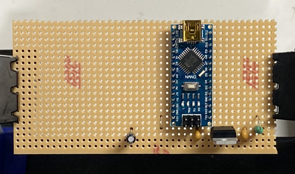
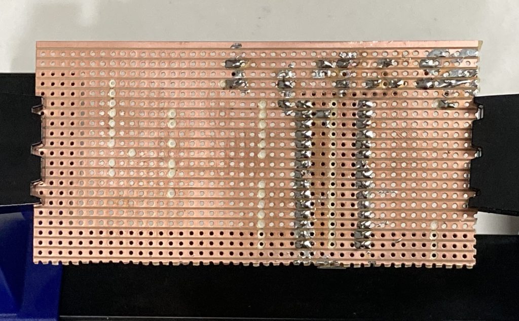
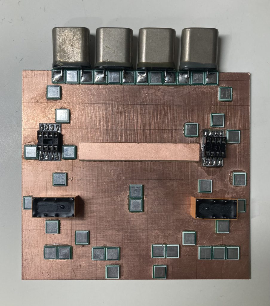
When I originally prepared the board I didn’t test the breaks in the traces for continuity, so before placing the components I checked them and there were a number of breaks which had continuity. After sorting the continuity I placed the power regulator first (and tested it), I then started to place the rest of the components.
I’m not all that happy with some of the soldering on this but I think its good enough and shouldn’t need redoing.
I’ve made a little progress on the IF board and started wiring up the relays, I also confirmed that they switch as expected with 12v. For the wiring, other than the 12v line, I used offcuts from components, however I’m not convinced that was the best move as it was somewhat tricky soldering them on to the relay and I’m concerned that I don’t have the best connections. I’ll take another look and if I don’t think they are good enough I’ll give them another go.
I’ve made a slow start on the IF board now, just the power regulation, decoupling capacitors and RF chokes. I was planning on connecting up and testing the relays too, but I got a bit confused on how to hook them up, I’m using DPDT relays hooked up in ‘SPDT mode’ so am holding off until I can get some assistance from the ScratchQRP group.
So far when doing Manhattan construction I’ve tended to have a general idea of where everything will go (much simplified thanks to the build documents on this project), I then start in one place and stick and solder as I go. This method has had the advantage of ensuring that in general pads are no closer/further apart than they should be and leads to a very neat layout assuming I don’t get the board size wrong.
For this module with it being larger and more complicated than the previous ones the “stick and go” method didn’t really seen viable, particularly as I couldn’t really start at one point and build across from there. This being the case using the layout and photos from the build document I’ve pre-stuck all the Manhattan pads and the relays and soldered the IC sockets into place. Next step will be to finally start the build!
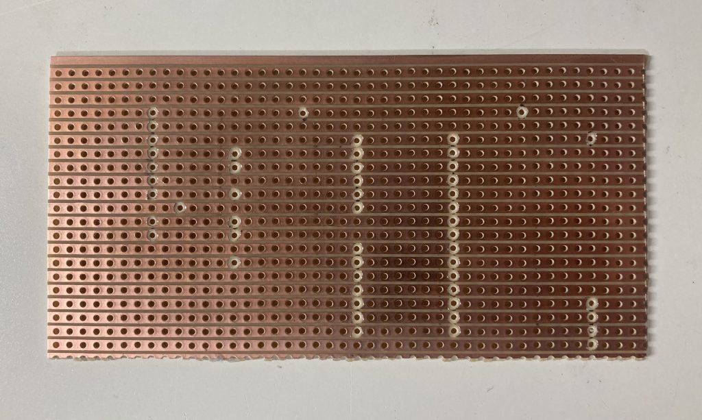
I’ve made no more progress on the IF board although I’ve ordered some QRPme MePads for mounting the ICs, once I have those I put the manhatten pads, relays and IC sockets in place. In the meantime I’ve started the board for the VFO/BFO module, I am using stripboard for this as it doesn’t lend itself well to manhatten style and G0FUW produced a layout for stripboard.
I cut the board to size, pencilled in the breaks and then used a small (3mm) drill bit to make the breaks in the strip. I need to test for continuity but am happy with how it’s turned out, I just need to solder the components on now!
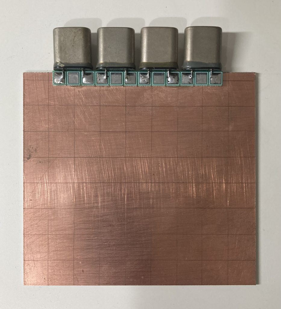
I’ve made a very tentative start to the IF board for the sudden transceiver project, it’s the largest and most complicated module (well it’s really a set of modules) so I’m taking stock as I try to figure the best way to attack it, however I’ve made a start by cutting the board, marking it out and attaching the crystals. I’ve used a few extra of the Manhattan squares to attach the crystals as one block.